
MODULAR WIRING REFERENCE
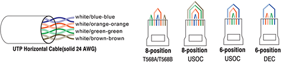
There are four basic modular jack styles. The 8-position modular outlets are commonly and incorrectly referred to as “RJ45”. The 6-position modular jack is commonly referred to as an RJ11. Using these terms can sometimes lead to confusion since the RJ designations actually refer to very specific wiring configurations called universal Service Order Code (USOC). The designation ‘RJ’ means Registered Jack. Each of these basic jack styles can be wired for different RJ configurations. For example, the 6-position jack can be wired as an RJ11C (1-pair), RJ(2-pair), or RJ25C (3-pair) configuration. An 8-position jack can be wired for configurations such as RJ61C(4-pair) and RJ48C. The keyed 8-position jack can be wired for RJ45S, RJ46S, and RJ47S. The fourth modular jack style is a modified version of the 6-position jack (modified modular jack or MMJ). It was designed by Digital Equipment Corporation (DEC) along with the modified modular plug (MMP) to eliminate the possibility of connecting DEC data equipment to voice lines and vice versa.
 |
 |
 |
 |
|
8-position |
8-position keyed |
6-position |
6-position modified |
MODULAR PLUG PAIR CONFIGURATIONS
it is important that the pairing of wires in the modular plug match the pairs in the modular jack as well as the horizontal and backbone wiring. If they do not, the data being transmitted may be paired with incompatible signals. Modular cords wired to the T568A color scheme on both ends are compatible with T568B systems and vice versa.

STRAIGHT-THROUGH OR REVERSED?
Modular cords are used for two basic applications. One application uses them for patching between modular patch panels. When used in this manner modular cords should always be wired “straight-through” (pin 1 to pin 1, pin 2 to pin 2, pin 3 to pin 3, etc.). The second major application used modular cords to connect the workstation equipment (PC, phone, GAX, etc). To the modular outlet. These modular cords may either be wired “straight-through” or “reversed” (pin 1 to pin 6, pin 2 to pin 5, pin 3 to pin 4, etc.) depending on the system manufacture’s specifications. This “reversed” wiring is typically used for voice systems. The following is a guide to determine what type of modular cord you have.
HOW TO READ A MODULAR CORD
Align the plugs side-by-side with the contacts facing you and compare the wire colors from left to right. If the colors appear in the same order on both plugs, the cod is wired “straight-through”. If the colors appear reversed on the second plug (from right to left), the cord is wired “reversed”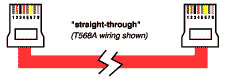
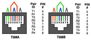
COMMON OUTLET CONFIGURATIONS
Two wiring schemes have been adopted by the “568-B.1 and “11801 standards. They are nearly identical except that pairs two and three are reversed. T568A is the preferred scheme because it is compatible with 1 or 2-pair USOC systems. Either configuration can be used for Integrated Services Digital Network (ISDN) and high speed data applications. Transmission categories 3, 5, 5e, and 6 are only applicable to this type of pair grouping.
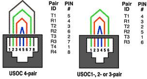
USOC wiring is available for 1-, 2-, 3-, or 4-pair systems. Pair 1 occupies the center conductors, pair 2 occupies the next two contacts out, etc. One advantage to this scheme is that a 6-position plug configured with 1, 2, or 3 pairs can be inserted into and 8-position jack and still maintain pair continuity. A note of warning though, pins 1 and 8 on the jack may become damaged from this practice. A disadvantage is the poor transmission performance associated with this type of pair sequence. None of these pair schemes is cabling standard compliant.
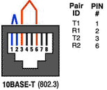
 10BASE-Twiring specifies and 8-position jack but used only two pairs. These are pairs two and three of T568A and T568B schemes.
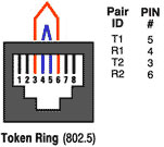
 Token Ring wiring uses either an 8-position or 6-position jack. The 8-position format is compatible with T568A, T568B, and USOC wiring schemes. The 6-position is compatible with 1- or 2-pair USOC wiring.
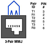
The MMJ is a unique wiring scheme for DEC equipment.
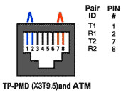
 ANSI X3T9.5 TP-PMD uses the two outer pairs of an 8-position jack. These positions are designated as pair 3 and pair 4 of the T568A wiring scheme. This wiring scheme is also used for ATM.
 CATEGORY 3
The characteristics are specified up to 16 MHz. It is typically used for voice and data transmission rates up to and including 10 Mbps, e.g. IEEE 802.5, 4 Mbps UTP and IEEE 802.3 10Base-T Ethernet
CATEGORY 4
The Characteristics are specified up to 20 MHz. It is typically used for voice and data transmission rates up to and including 16 Mbps, e.g. IEEE 802.5, 4/16 Mbps UTP.
CATEGORY 5
The characteristics are specified up to 100 MHz. It is typically used for voice and data transmission rates up to and including 100 Mbps, e.g. IEEE 802.5, 16 Mbps UTP, ANSI X3T9.5 100 Mbps TPDDI, 100Base-TX and 155 Mbps ATM.
CATEGORY 5e
The characteristics are specified up to 100 MHz. It supports Fast Ethernet, 155 Mpbs ATM and Gigabit Ethernet. It has Power Sum performance designed for any combination of transmission schemes and a minimum of 3 dB headroom from Category 5.
CATEGORY 6
The characteristics are specified up to 250 MHz. At the time of this writing, Category 6 is currently a proposal only and its subject to change. Standards should be defined at a future date.
ACR
Attenuation to Near-End Crosstalk Ratio (ACR) is the difference between the crosstalk and the attenuation. Improved ACR provides additional performance and leads to the development of higher bandwidth and increased data rate transmission protocols.
ATTENUATION
Attenuation is a measure of signal power loss due to the connecting hardware and is derived from swept frequency voltage measurements on short lengths of 100 Ohm twisted-pair leads before and after inserting the connector under test.
NEXT
Next is a measure of signal coupling from one circuit to another within a connector and is derived from swept frequency voltage measurements on short lengths of 100 meters (twisted-pair test leads terminated to the connector under test). A balanced input signal is applied to a disturbing pair of the connector while the induced signal on the disturbed pair is measured at the near-end of the test leads.
POWER SUM CROSSTALK
Power Sum crosstalk is the addition of the crosstalk power from several transmitting signals on different pairs. Power Sum NEXT (near-end crosstalk) and FEXT (far-end crosstalk) compliance ensures that a cabling channel will not exceed crosstalk performance requirements when all four pair are operating simultaneously such as in the Gigabit Ethernet
FEXTF
ar-End Crosstalk (FEXT) is the noise induced by a transmitter at the near end into the far end receiver due to unwanted signal coupling. FEXT can be a factor in multi-pair, bi-directional signaling such as Gigabit Ethernet.
RETURN LOSS
Return loss is the reflected signal power of a transmitted signal. Better return loss improves signal integrity and increases performance for dual-duplex transmissions.
What type of copper cable should be used when connecting Fast Ethernet networks?
For 100Base-TX or 100Mbps networking, JE recommends Category 5e cable.
What is UTP and STP mean?
UTP stands for Unshielded Twisted Pairs and STP stands for Shielded Twisted Pair.
What is a crossover cable?
A crossover cable is a 2-pair cable that crosses over pins 1,2/3,6. This cable is normally used to connect 2 computers directly or cascade 2 hubs without the use of an uplink port.
Can you use telephone patch cords to connect a LAN?
Using telephone cords to connect a LAN is not recommended. Telephone cords are designed to work with low speed applications such as voice transmission.
Do you need a special tool when working with 110-Type patch panels and jacks?
Yes, you need to use a 110-Type impact tool in order to properly terminate your connections.
Do you need a hub if using coaxial cable on a LAN?
No, a hub is not needed when you are using coaxial cable. You can directly connect each computer by using coaxial cable but you must put terminators on each end of the cable.
What is Crosstalk?
Crosstalk is the unwanted introduction of signals from one channel or pair to another.
What is difference between a “Channel” and a “Link”?
These terms describe two Category certification tests. These tests differ in how much of a horizontal cabling run is included for testing. The basic difference is that a link includes patching and /or equipment cords as well.
What effect does workmanship and equipment have upon cabling performance?
One reason why channel and link tests have evolved has to do with the quality of the workman ship and materials. Channel performance is greatly affected by cable characteristics, connecting hardware, patch cords and cross-connect wiring, as well as the total number of connections and the care with which they are installed and maintained. You can go a long way toward preserving performance by simply choosing good quality components and installing them with care and proper techniques.
Why should I test the cable immediately after pull-in?
This simplifies subsequent troubleshooting. By testing the system at this point, should a problem arise after the equipment is installed, the cabling system can be ruled out as a probable cause.
10Base-2 – A variant of Ethernet, connecting stations via thin coaxial cable; maximum cable distance in one non-repeated segment is 185 meters.
10Base-5 – A variant of Ethernet, connecting station via thick coaxial cable; maximum cable distance in one non-repeated segment is 500 meters.
10Base-FL – A variant of Ethernet, connecting stations via fiber optic cabling.
10Bast-T – A variant of Ethernet, connecting stations via twisted pair cabling.
100Base-FX – A variant of Ethernet which runs on multi-mode or single mode fiber optic cabling at 100Mbps. This is one version of Fast Ethernet.
100Base-TX – A variant of Ethernet which runs on Category 5 unshielded twisted pair wiring at 100Mbps. This is one version of Fast Ethernet.
1000BaseX-C – A variant of Gigabit Ethernet which runs on twinaxial cable.
1000Base-LX – A variant of Gigabit Ethernet which runs on multi-mode and single mode fiber optic cable at a 1330 um frequency.
1000Base-SX – A variant of Gigabit Ethernet which runs on multi-mode fiber optic cable at an 850 um frequency.
1000Base-T – A variant of Gigabit Ethernet which runs on unshielded twisted pair cable.
|
3PThird
Third Party Testing, in Denmark
ACR
Attenuation-to-crosstalk ratio
ADO
Auxiliary disconnect outlet
ADSL
Asynchronous Digital Subscribes Line
ANSI
American National Standards Institute
ATM
Asynchronous transfer mode
AWG
American wire gauge
BD
Building distributor
BER
Bit Error Rate
BFOC
Bayonet Fiber Optic Connector
b/s
Bit per second
CD
Campus distributor
CDDI
Copper Distributed Data Interface
CM
Common mode
CP
Consolidation point
CPE
Customer premises equipment
CSA
Canadian Standard Association
dB
Decibel
DD
Distribution device
EF
Entrance facility
EIA
Electronics Industries Alliance
ELFEXT
Equal level far-end crosstalk
EMC
Electromagnetic compatibility
EMI
Electromagnetic interface
EMR
Electromagnetic radiation
ER
Equipment room
FCC
Federal Communication Commission
FD
Floor distributor
FDDI
Fiber Distributed Data Interface
ft
Feet
FEXT
Far-end crosstalk
FIPS PUB
Federal Information Processing Standard Publication
FTP
Foil twisted pair
Gb/s
Gigabit per second
GHz
Giga hertz
HC
Horizontal cross-connect
HVAC
Heating, ventilation and air condition
Hz
Hertz
IC
Intermediate cross-connect
IDC
Insulation displacement connection
IDF
Intermediate Distribution Frame
IEC
International Electrotechnical Commission
|
ISDN
Integrated Services Digital Network
ISO
International Standard Organization
JTC
Joint technical committee
Kb/s
Kilobit per second
Km
Kilometer
KYS
Key telephone system
LAN
Local area network
lbf
Pounds force
LEC
Local exchange carrier
LED
Light emitting diode
M
Meter
um
Micron; 0.000001; also micrometer
Mb/s
Megabits per second
MC
Main cross-connect
MDF
Main distribution frame
MHz
Mega Hertz
mmr
Millimeter
MT-RJ
Mechanical Transfer Registered Jack
NEC
National Electrical Code
NEMA
National Electrical Manufacturers Association
NEXT
Near-end crosstalk
NFPA
National Fire Protection Association
nm
Nanometer
PBX
Private branch exchange
PVC
Polyvinyl chloride
RF
Radio frequency
RMS
Rack mount space
SC
Subscriber connector
ScTP
Screened twisted pair
SOHO
Small office home office
STP
Shielded twisted pair
TIA
Telecommunications Industry Association
TO
Telecommunications outlet
TP
Transition point
TP-PMD
Twisted-Pair Physical Media Dependent
TPDDI
Twisted-Pair Distributed Data Interface
TSB
Telecommunications System Bulletin
UL
Underwriters Laboratories Inc.
UPS
Uninterruptible power supply
USOC
Universal Service Order Code
UTP
Unshielded twisted pair
WA
Work area
IEEE
Institute of Electrical and Electronic Engineers
|
| IEC 61755-3-2-2006 | Fibre optic connector optical interfaces – Part 3-2: Optical interface, 2,5 mm and 1,25 mm diameter cylindrical full zirconia ferrules for 8 degrees angled-PC single mode fibres |
| EC 61755-2-2-2006 | Fibre optic connector optical interfaces – Part 2-2: Optical interface standard single mode angled physically contacting fibres | ||
| IEC 60332-1-3-2004 | Tests on electric and optical fibre cables under fire conditions – Part 1-3: Test for vertical flame propagation for a single insulated wire or cable – Procedure for determination of flaming droplets/particles | ||
| IEC 60332-1-2-2004 | Tests on electric and optical fibre cables under fire conditions – Part 1-2: Test for vertical flame propagation for a single insulated wire or cable – Procedure for 1 kW pre-mixed flame | ||
| IEC 60332-1-1-2004 | Tests on electric and optical fibre cables under fire conditions – Part 1-1: Test for vertical flame propagation for a single insulated wire or cable – Apparatus | ||
| IEC 61034-2-2005 | Measurement of smoke density of cables burning under defined conditions – Part 2: Test procedure and requirements | ||
| IEC 61034-1-2005 | Measurement of smoke density of cables burning under defined conditions – Part 1: Test apparatus | ||
| IEC 60754-2-1991 | Test on gases evolved during combustion of electric cables – Part 2: Determination of degree of acidity of gases evolved during the combustion of materials taken from electric cables by measuring pH and conductivity | ||
| IEC 60754-1-1994 | Test on gases evolved during combustion of materials from cables – Part 1: Determination of the amount of halogen acid gas | ||
| IEC 61300-3-30-2003 | Fibre optic interconnecting devices and passive components – Basic test and measurement procedures – Part 3-30: Examinations and measurements – Polish angle and fibre position on single ferrule multifibre connectors | ||
| IEC 61300-3-23-1998 | Fibre optic interconnecting devices and passive components – Basic test and measurement procedures – Part 3-23: Examination and measurements – Fibre position relative to ferrule endface | ||
| IEC 61754-4-2002 | Fibre optic connector interfaces – Part 4: Type SC connector family | ||
| IEC 61754-4-1-2003 | Fibre optic connector interfaces – Part 4-1: Type SC connector family – Simplified receptacle SC-PC connector interfaces | ||
| IEC 61753-1-2007 | Fibre optic interconnecting devices and passive components performance standard – Part 1: General and guidance for performance standards | ||
| IEC 61754-20 | Fibre optic connector interfaces – Part 20: Type LC connector family | ||
| IEC 61754-13 | Fibre optic connector interfaces – Part 13: Type FC-PC connector | ||
| IEC 61754-15 | Fibre optic connector interfaces – Part 15: Type LSH connector family | ||
| IEC 61754-3 | Fibre optic connector interfaces – Part 3: Type LSA connector family | ||
| IEC 61754-2 | Fibre optic connector interfaces – Part 2: Type BFOC/2,5 connector family | ||
| IEC 61754-18 | Fibre optic connector interfaces – Part 18: Type MT-RJ connector family | ||
| IEC 61753-2-1 | Fibre optic interconnecting devices and passive components performance standard – Part 2-1: Fibre optic connectors terminated on single-mode fibre for category U – Uncontrolled environment | ||
| TIA-604-4-B-2004 | Fiber optic connector intermateability standard, type FC and FC/APC | ||
| Telcordia GR-326-CORE | Generic requirements for singlemode optical connectors and jumper assemblies | ||
| BS EN60793-2-2004 | Optic fibers-part2:Product specifications general | ||
| TIA/EIA-455-1B | Cable Flexing for fiber optic interconnecting devices | ||
| TIA/EIA-604-10A | Fiber optic connector intermateability standard type LC | ||
| TIA/EIA-455-107A | Determination of component reflectance or link/system return loss using a loss test set | ||
| TIA/EIA-604-3A | Fiber optic connector intermateability standard type sc | ||
| GR-910-CORE | Generic requirements for fiber optic attenuators | ||
| GR-409-CORE | generic requirements for premises fiber optic cable | ||
| TIA/EIA-604-12 | fiber optic connector intermateability standand type MTRJ | ||
| TIA/EIA-604-12A | MTRJ | ||
| TIA/EIA-568-B.3 | optical fiber cabling components standard | ||
| TIA TSB125-2001 | guidelines for maintaining optical fiber polarity through reverse-pair positioning | ||
| IEC 61300-3-4-2001 | Fibre optic interconnecting devices and passive components – Basic test and measurement procedures – Part 3-4: Examinations and measurements – Attenuation | ||
| IEC 61300-3-6-2003 | Fibre optic interconnecting devices and passive components – Basic test and measurement procedures – Part 3-6: Examinations and measurements – Return loss | ||
| ICEA S-83-596-2001 | OPTICAL FIBRE PREMISES DISTRIBUTION CABLE | ||
| IEC 60793-1-31-2001 | Optical Fibres – Part 1-31: Measurement Methods and Test Procedures – Tensile Strength-First Edition | ||
| IEC 60793-1-32-2001 | Optical fibres – Part 1-32: Measurement methods and test procedures – Coating strippability | ||
| IEC 60793-1-30-2001 | Optical fibres – Part 1-30: Measurement methods and test procedures; Fibre proof test | ||
| IEC 60793-1-53-2001 | Optical fibres – Part 1-53: Measurement methods and test procedures – Water immersion | ||
| IEC 60793-1-20-2001 | Optical fibres – Part 1-20: Measurement methods and test procedures – Fibre geometry | ||
| IEC 60793-2-2003 | Optical fibres – Part 2: Product specifications – General | ||
| TIA-598-C-2005 | Optical Fiber Cable Color Coding |